
Below are the wiring diagrams for 3Dtek specific Gecko G540 Applications.
These may or may not be useful for other Gecko use cases. Please contact 3DTek for any assistance wiring up or configuring these devices.
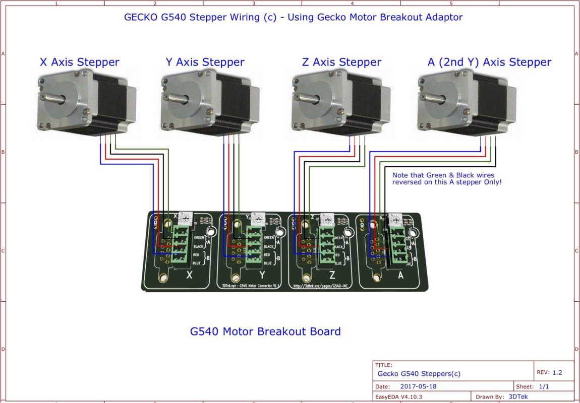
Stepper Motor Connections (c) G540 Motor Connector Board Method<
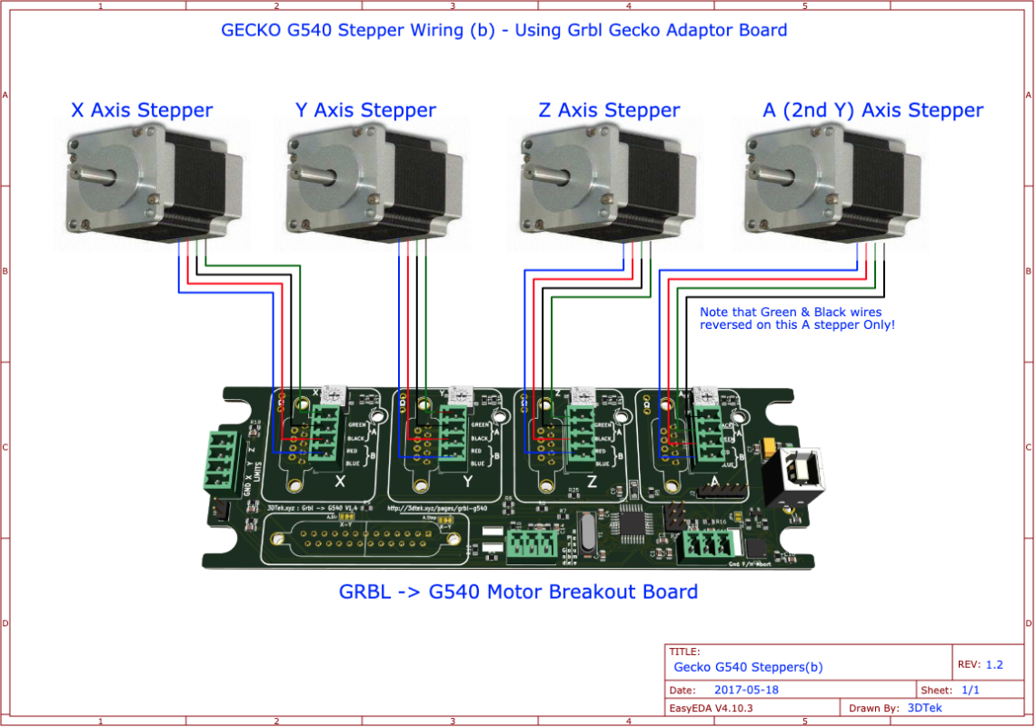
Stepper Motor Connections (b) GRBL -> G540 Motor Breakout Board Method
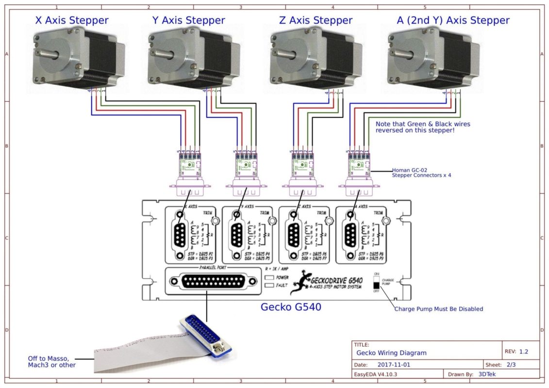
Stepper Motor Connections (a) Retired method.
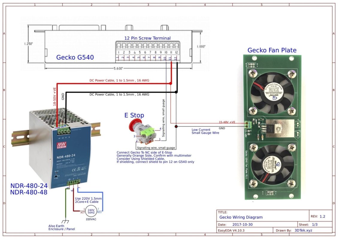
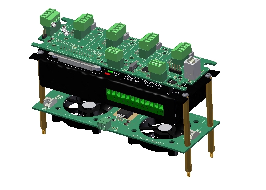
Gecko, Cooler and controller Mounting
- The Gecko G540 and Cooler are mounted and separated using standoffs.
- The Cooler plate sits below the G540 on its shorter standoffs, with the fan’s sticker side facing the bottom of the G540
- The Control Card or Motor Connector is pressed onto the top of the G540 and holds its self in place firmly.