

Diagrams Below are the wiring diagrams for 3Dtek specific Masso Applications.
These may or may not be useful for other Masso use cases. Please contact 3DTek for any assistance wiring up or configuring these devices.
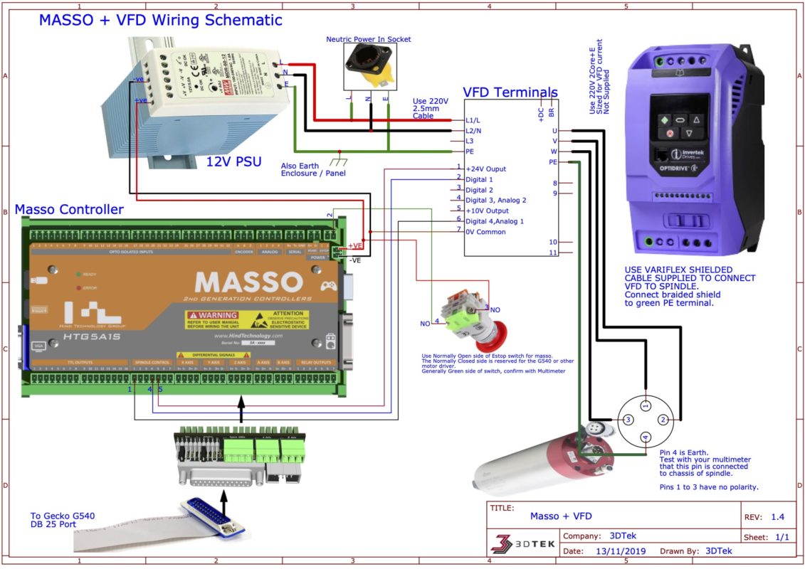
MASSO POWER AND VFD CONNECTIONS
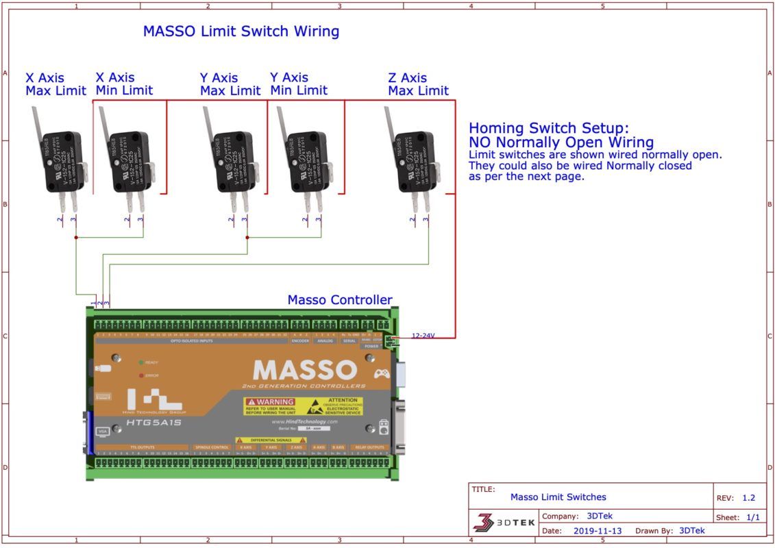
MASSO LIMIT SWITCH WIRING
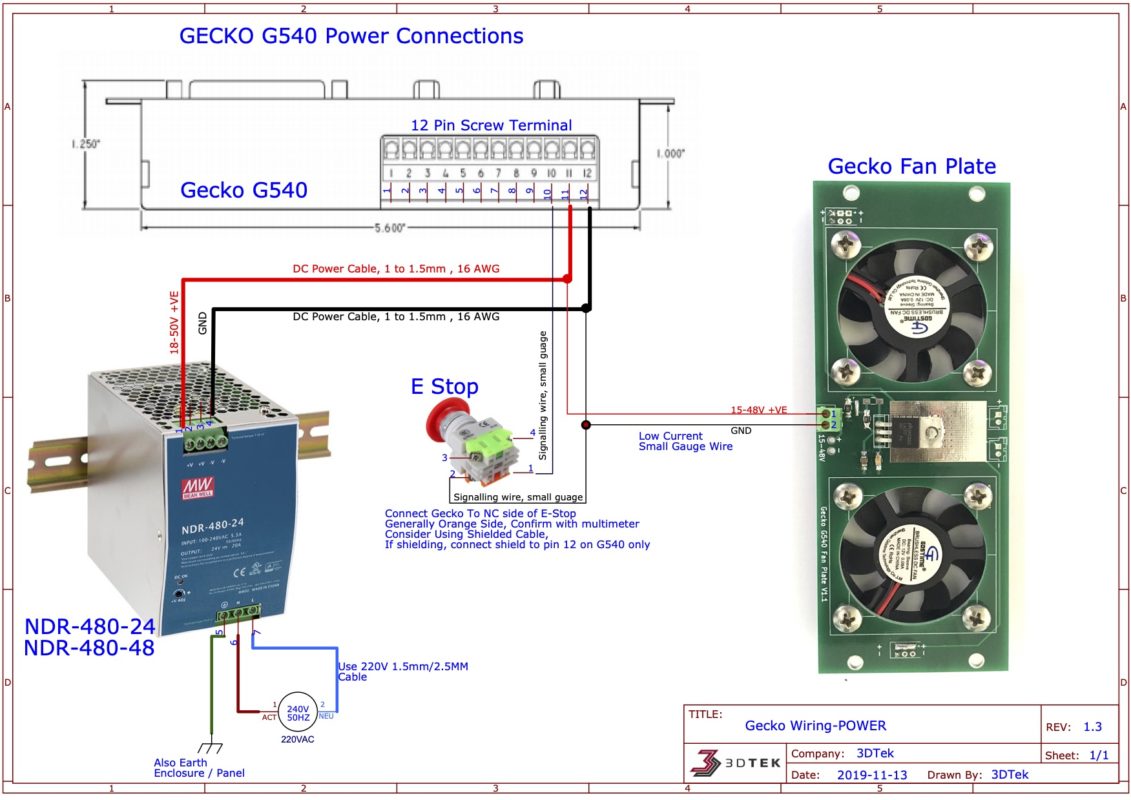
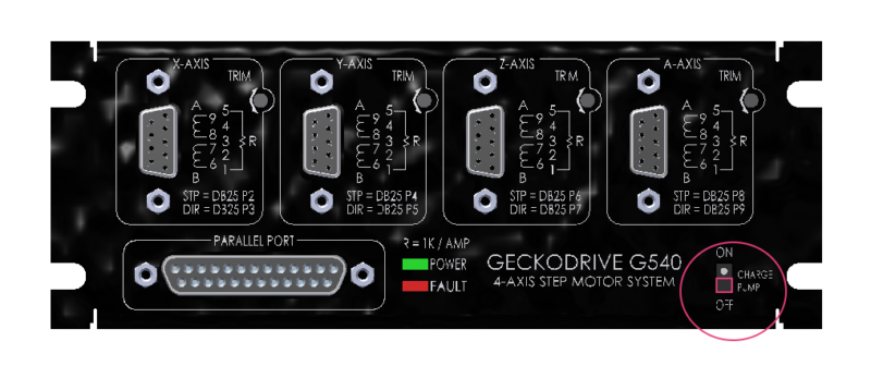
Gecko G540 POWER Wiring
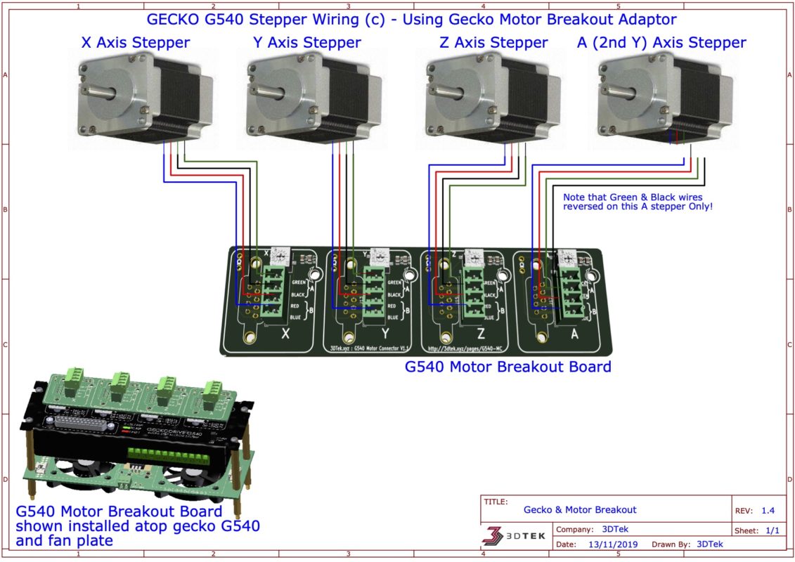
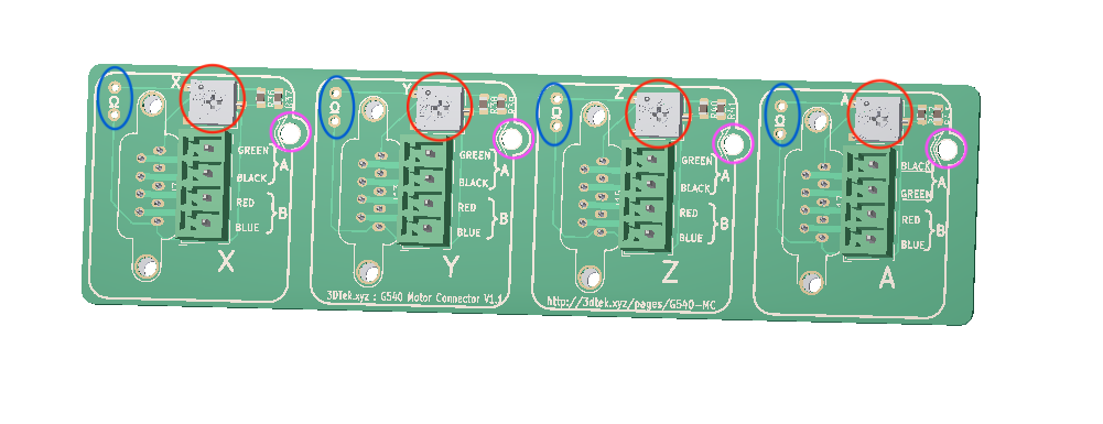
GECKO G540 MOTOR WIRING
Gecko, Cooler and Motor Connector Mounting
- The Gecko G540 and Cooler are mounted and separated using standoffs.
- The Cooler plate sits below the G540 on its shorter standoffs, with the fan’s sticker side facing the bottom of the G540
- The Control Card is pressed onto the top of the G540 and holds its self in place firmly.
- The cooler will be marked for either 12V or 12-48V connection.

- The GRBL Gecko Motor Connector has a trim pot for setting the current limiting of each stepper motor which are circled red in the image below. This takes place of the resistor to be soldered that is mentioned in the G540 manual. Note that this is not smoothness tuning the trim pot mentioned in the manual.
- There is also measurement point beside each trim pot marked in blue. The desired resistance measurement between the two terminals is 2.5 to 3kOhm. If your motors are running overly hot then turn this down a little, if you are suffering from lack of power turn this up a little.
- Lastly, an opening in the board to access the smoothness adjust trim pot, which can largely be ignored. see the gecko manual linked above for information on its use.
Gecko Setup
Please ensure the charge pump switch on the gecko is turned off.
Please note that you will not need to follow any of the information in the gecko manual regarding current tuning (resistor selection). This is covered with the trim pots on the GRBL Gecko Motor Connector.
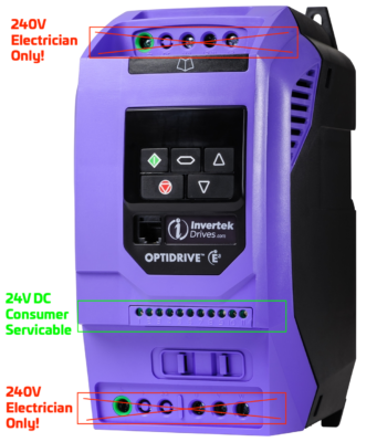
VFD Spindle Controller
The invertek E3 VFD has several important and several optional parameters to be set before attempting to operate.
Reference: E3 User guide
IMPORTANT NOTES
- The VFD Wiring Diagram above is for your electrician! 240V wiring and VFD’s are so very dangerous, please don’t risk doing this yourself.
- Your electrician is welcome to call 3Dtek with any questions
- The supplied speciality VFD cable must be used
- The Shielded braid of the VFD cable should be connected to the PE (earth) on the VFD along with wire 4 to achieve best noise suppression.
- The VFD that this is potentially a very dangerous device that is designed to be commissioned by a licensed electrician. The image below shows the separation of Low and High voltage, ie which parts are safe for user access and which are not.
- Regardless of the fact you may not be intending to come in to contact or modify the high voltage areas of the device – they are there and accessible! And so ask the electrician to program and complete the entire setup so that you have no reason to interact with this device. Any wiring changes to the VFD must be done after ensuring the machine has been isolated from the power for 10 minutes.
Configuring the E3
The following information configures the E3 for 3DTeks standard use case and this information may not be appropriate for other uses.
The following diagram describes the control pad functions of an E3 inverter, as described in section 5 of the manual:

To program any parameter, press and hold the navigate button for a few seconds, at which point the keypad will display the last parameter configured, initially 1.
You may use the up and down arrows to skip to a new parameter and a short press of the navigate button to enter and exit a parameter.
For example, to set our first and most important parameter P-08 (Motor Rated Current):
- Long press on the navigate button to enter programming mode
- up or down arrow until P-08 is displayed
- a short press on the navigate button to enter into this parameter
- up or down arrow to set the desired motor rated current, as displayed on the spindle it’s self (10.0 for the 2.2KW spindle)
- then a further short press of the navigate button to exit this parameter – our new value is saved at this point.
- Another long press of the navigate button to exit programming mode altogether.
Before attempting to operate the VFD, please set the following params – in this order:
- P-08 – Motor Rated Current: Nameplate current rating as printed on spindle motor. (10.0 for 2.2kw, 7.0 for 1.5KW, 5.0 for 800W)
- P-07 – Motor Rated Voltage: Nameplate voltage = 220V
- P-09 – Motor Rated Frequency: Nameplate freq: 400 Hz
- P-10 – Motor Rated Speed: Nameplate rpm: 24,000 (careful not to set it at 2,400)
- P-01 – Maximum Frequency: Check at this point that 24000 has been saved here for you
- P-14 – Extended Access: 201
- P-12 – Primary Command Source: 0
- P-30 – Start Mode: Auto-0 (note that you get two random answers on the display when exiting this parameter, ignore them)
- P-51 – Motor Control Mode: 1 (V/f mode)