
This post is about configuring the GRBL AIO Versions 1.I and later – for versions prior to 1.I, please see GRBL AIO Configuration Pre V1.I

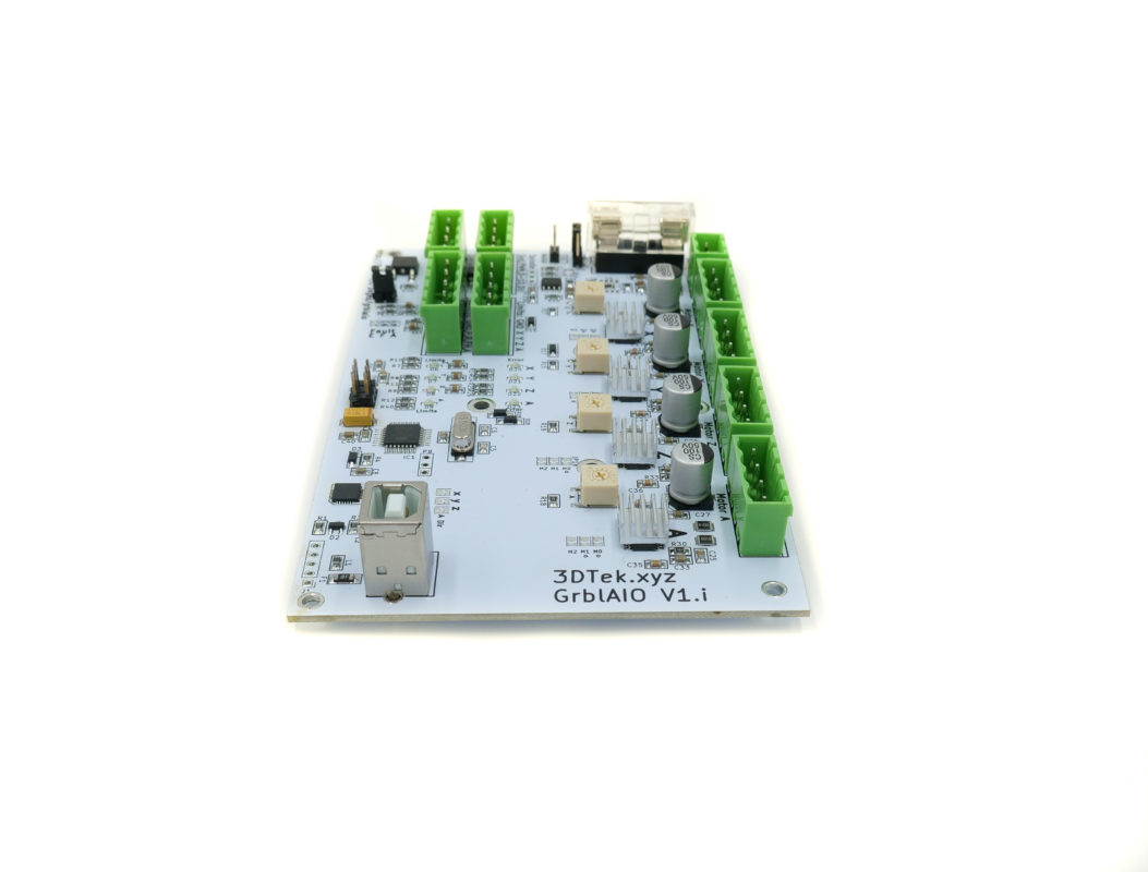
Main Connections Detailed
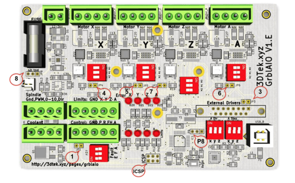
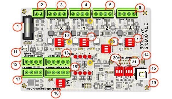
- Fuse – 5x20mm – Suggested 6.3-7.5A 5mm Diameter x 20mm Length. This fuse acts on the 12-36V motor power circuit.
- 12-36V DC power in. The DRV8825 Drivers can actually handle up to 45V, 36v, however, is the largest standard voltage power supply readily available. There is merit to running the Steppers at as high a voltage as practical (within reason) however 24V is plenty. The regulator for 12V fan power and 0-10V VFD output will work harder at higher voltages and has been selected for 36V max hence the 36V max on the power supply.
- X Motor output, one motors coil pairs on the left side, other on the right side *1
- Y Motor output, one motors coil pairs on the left side, other on the right side *1
- Z Motor output, one motors coil pairs on the left side, other on the right side *1
- A Motor output (usually tandem with Y), one motors coil pairs on the left side, other on the right side *1 *2
- A Micro step M0 / M1 / M2, Generally On On Off.
- Z Micro step M0 / M1 / M2, Generally On Off Off.
- Y Micro step M0 / M1 / M2, Generally On On Off
- X Micro step M0 / M1 / M2, Generally On On Off
- Fan Connector, to connect your fan if using one, note voltage selector on JP8
- Spindle control output, GND & PWM runs a pulse width signal for controlling DC spindle speed controllers and alike, GND & 0-10 runs a 0-10V signal for controlling the speed of a VFD. Direction goes high or low to suggest direction (not generally used) – PLEASE SEE SPINDLE PORT DETAILS BEFORE CONNECTING A PWM SPINDLE OR LASER CONTROLLER – To avoid damage to your equipment!!!
- Limit Switch Inputs, GND is common across all switches, X, Y, &, Z go generally on the normally open side of limit switches. If using multiple limit switches per axis there may be two wires into each X Y & Z – The A limit pin is unused.
- External driver outputs, connect a DB 15 socket here or solder in wires manually to access the Enable, Step, and Direction outputs for each X Y and Z axis (enable pin is common across all)
- USB IO – you guessed it, stick the USB cable in here.
- CNC Control (Probe / Resume /Feed Hold / Estop) These have a common ground and are connected to buttons or switches in normally open config.
- Coolant Control, Detailed Info
- Fault Logic -F = Feed hold on an error, A = abort/reset on an error, E feeds to a spare pin on the Arduino that could be set up as a separate error condition in code. For Motor driver faults to activate fault conditions, the jumpers 4, 5, 6, &/or 7 need to be connected.
- 19 Mounting screw holes – self-explanatory again
- A Direction will be duplicated from either X, Y, Or Z
- A Steps will be duplicated from either X, Y, Or Z
WIRING
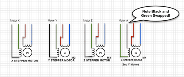
Stepper Motors
*1 Our motors use Black + Green as one pair, and Blue + Red as the other. When connecting to the motor connectors, keep one pair on one side of the plug and the other pair on the other side of the plug – so for example left to right: Black Green Red Blue.
*2 The A motor often requires running in the opposite direction to the X or Y motor that its tandem driven with. (True for Heavy Mill & X Carve). If so then for this motor reverse one of the pairs of wires, so for this one left to right: Green Black Red Blue. Note the Green and Black have swapped position here.
Limit Switches
Limit switch port (13) has 5 pins. We will ignore the 5th pin labelled “A” this is for future use.
If setting up an XYZ carve, you will only have 3 limit switches and so can ignore that labelled X2, Y2 and Z2
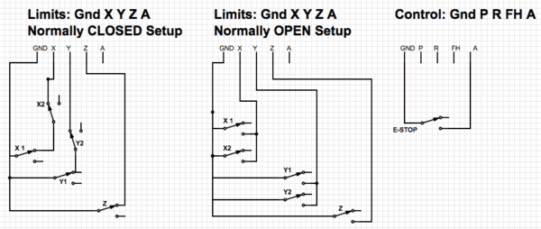
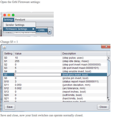
Limit switches in GRBL are by default normally open, which is highly unusual but the standard with this software. Wire them either way as per below however if you go normally closed you will need to change a parameter in GRBL as per below:
Spindle Port Details
The spindle port has slightly different functionality depending on the version of the card and it’s important to understand the voltage levels of your spindle/laser controller and the AIO card before making connections.
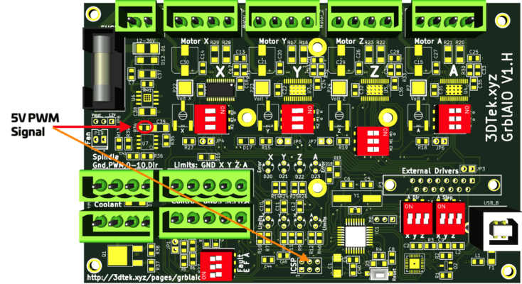
VER 1 to V 1.H: Early on in the history of this card, available DC spindle drivers were 12V PWM tolerant and so the PWM spindle pin output a 12V PWM signal. Cards with versions up to 1.H will have a 12V PWM output and should not be connected to Laser or Spindle drivers that can only take TTL (5V) inputs. If it’s necessary to connect one of these the only option is to solder a wire onto R34 or use the centre top pin on the ICSP header to tap into the 5V PWM signal – both identified in the image below. If you’re not comfortable doing so you are welcome to return the card to 3Dtek for a connection to be added or the card to be swapped out for a later version if stock permits.
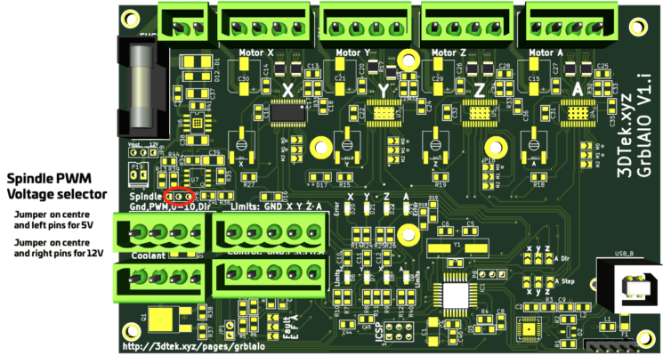
Ver 1.i and later: From V 1.i there is a PWM spindle output voltage selector circled below. Putting a jumper on the centre and left pins enables 5V PWM output on the PWM pin and a jumper on the centre and right pins give 12V PWM output on the PWM pin.
In addition, for some versions/production batches of the AIO card, we have opted not to populate the 12V regulator that manages the 0-10V and 12V PWM options. Again if the functionality you require cannot be managed you are welcome to send the card to 3Dtek for an update.
Jumpers
Jumper Options
- JP1 – Breaks Z Limit switch filter which is also on the MISO line and so can be troublesome if present while uploading code or boot loading via ICSP. Disconnect during programming via ICSP, reconnect for normal operation.
- JP3 – Connected if using onboard drivers, disconnected if using external drivers
- JP4 – Connect to enable X driver fault processing *3
- JP5 – Connect to enable Y driver fault processing *3
- JP6 – Connect to enable A driver fault processing *3
- JP7 – Connect to enable Z driver fault processing *3
- JP8 – Fan power, Connect in the right position for 12V, left to match PSU voltage
- P8 – Not used yet
- ICSP – In-circuit system programming header (for boot loading etc)
Driver current setting pots
- X Driver current limiting trim pot
- Y Driver current limiting trim pot
- Z Driver current limiting trim pot
- A Driver current limiting trim pot
These pots reduce current output of drivers when turned clockwise.
Dip Switch Settings
- 10: X Microstep M0 / M1 / M2, Generally On On Off, Setting the driver to 1/8th microstepping (8 Microsteps per step pulse received)
- 9: Y Microstep M0 / M1 / M2, Generally On On Off, Setting the driver to 1/8th microstepping (8 Microsteps per step pulse received)
- 8: Z Microstep M0 / M1 / M2, Generally On Off Off, Setting the driver to 1/2th microstepping (2 Microsteps per step pulse received)
- 7: A Microstep M0 / M1 / M2, Generally On On Off, Setting the driver to 1/8th microstepping (8 Microsteps per step pulse received)
- 18: Faults, No switch populated (Future Use, Contact us for more info)
- 20: A Direction, only one switch can be on, X, Y, Or Z. Whichever switch is on the DIRECTION signals for that axis will be duplicated to the A Axis, for our machines we select Y to tandem the direction from our Y axis over to the A.
- 21: A Step, only one switch can be on, X, Y, Or Z. Whichever switch is on the STEP PULSE signals for that axis will be duplicated to the A Axis, for our machines we select Y to tandem the Step Pulses from our Y axis over to the A.
Drivers:
The AIO card uses a Silicon Labs USB chipset, download drivers for your system here
OSX Note: Using later versions of ‘Universal Gcode Sender‘, you will need to change the name of the serial port manually instead of selecting it from the drop-down. Paste in “/dev/tty.SLAB_USBtoUART” to the port field.
Select a Baud Rate of 115200
GRBL Control Software Interface
There are many, the most simple and widely used is Universal G-Code Sender, grab the platform version. It’s in the downloads section 1/2 way down the page.
NOT the green ‘clone or download’ button!!! That’s an uncompiled version.