
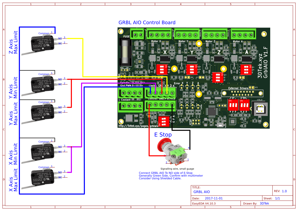
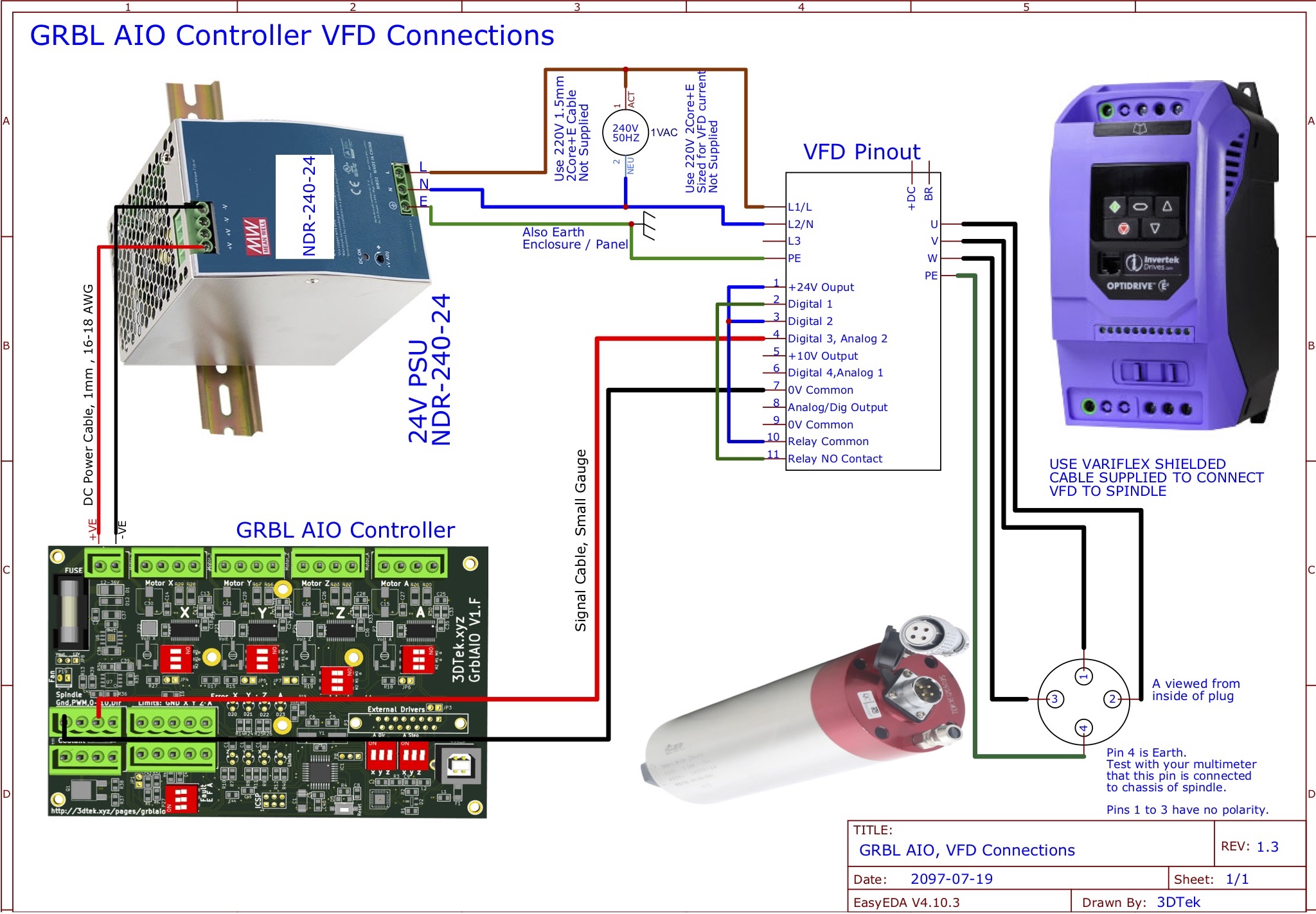
Wiring diagrams for 3DTEK VFD Spindle and AiO Card
PLEASE READ IMPORTANT NOTES AT BOTTOM BEFORE POWERING UP THE VFD!!!! DO NOT POWER ON THE SPINDLE BEFORE FULLING CHECKING CURRENT SETTINGS ARE CORRECT IN THE VFD!!!
These wiring diagrams take into account that a 0-10v signal will be supplied to the Invertek VFDs 3DTEK supply.
Please contact 3DTek for any assistance wiring up or configuring these devices. Please see also the main AIO configuration page for more information.
IMPORTANT NOTES
- The VFD Pinout Wiring Diagram above is for your electrician! 240V wiring and VFD’s are so very dangerous please don’t risk doing this yourself if you are not equipped to do so.
- Your electrician is welcome to call 3Dtek with any questions
- The supplied speciality VFD cable must be used
- The Shielded braid of the VFD cable should be connected to the PE (earth) on the VFD along with wire 4 to achieve best noise suppression.
If you get and “L” flash up on the VFD while setting any parameters, please momentarily disconnect the wire from terminal 1 whilst making the parameter updates and reconnect when finished.
Speciality VFD cable should be used and its shielding should also be terminated to the VFD’s PE Ground Terminal.
Please note, all spindles are ground and tested (0-400Hz range) before issue.
To program any parameter, press and hold the navigate button for a few seconds, at which point the keypad will display the last parameter configured, initially 1.
You may use the up and down arrows to skip to a new parameter and a short press of the navigate button to enter and exit a parameter.
For example, to set our first and most important parameter P-08 (Motor Rated Current):
- Long press on the navigate button to enter programming mode
- up or down arrow until P-08 is displayed
- a short press on the navigate button to enter into this parameter
- up or down arrow to set the desired motor rated current, as displayed on the spindle it’s self (10.0 for the 2.2KW spindle)
- then a further short press of the navigate button to exit this parameter – our new value is saved at this point.
- Another long press of the navigate button to exit programming mode altogether.
Before attempting to operate the VFD, please set the following parameters – in this order:
- P-08 – Motor Rated Current: Nameplate current rating (printed on spindle motor) IMPORTANT: DO NOT SET WRONG CURRENT (10.0 (10amps) for 2.2kw, 7.0 (7amps) for 1.5KW, 5.0 (5amps) for 800W)
- P-07 – Motor Rated Voltage: Nameplate voltage (printed on spindle) = 220V
- P-09 – Motor Rated Frequency: Nameplate frequency: 400 Hz (NOTE: Ensure this reads on your VFD 400.0, not 40.0)
- P-10 – Motor Rated Speed: Nameplate rpm: 24,000 (careful not to set it at 2,400)
- P-01 – Maximum Frequency: Check at this point that 24000 has been saved here for you
- P-14 – Extended Access: 201
- P-12 – Primary Command Source: 0 (zero) NOTE: We set this to 1 when using the VFD in keypad mode. Pins 1 + 2 need to be shorted in this instance
- P-15 – Digital Input Function Select: 4
- P-18 – Output Relay Function Select: 8
- P-19 – Relay Threshold Level: 15
- P-30 – Start Mode: Auto-0 (note that you get two random answers on the display when exiting this parameter, ignore them)
- P-51 – Motor Control Mode: 1 (V/f mode)